1. The following specification summary is for the MEMS accelerometers that are currently supplied by Analog Device Inc. Please make the similar specification for an obsolete one, ADXL05. Check out ADXL05 datasheet from http://memsliu.pme.nthu.edu.tw/~liuch/transducer/ADXL05_datasheet.pdf Figure out the specifications - Transfer Function, Sensitivity, Dynamic Range, Hysteresis, Temperature Effect, Linearity, Accuracy, Noise, Resolution, Bandwidth etc. (also the specifications listed on the following specification summary table) Some of these specifications might not be specified on the datasheet. Some of above specifications might have multiple definitions from one book to another book. However, do your best to figure out most of them and give your definition if there might be some confusion.
Sol:
ADXL05 specification table
| Parameter (Units) | Value | Conditions and Ref. | |
| Of Axes | 1 ( X axes) | From Ref. [1] ( From Ref. [2]) | |
| Range (g) | ± 5 g | From Ref. [1] | |
| Sensitivity (V/g) | 0.2 V/g | @25℃, From datasheet | |
| Transverse Sensitivity (%) | ± 2 % | From datasheet | |
| Sensitivity Accuracy (%) | ± 12.5 % | @+25 ℃, From datasheet | |
| Output Type* | Analog | From Ref. [1] | |
| Max Band Width (kHz) | 6 kHz | @ c1=0.010µF, From datasheet page 2 Note 4 | |
| Noise Density | - | Can't be specified | |
| Voltage Supply (V) | +5V (+ 4.75 V ~ + 5.25 V) | From datasheet | |
| Supply Current (mA) | 10 mA | From Ref. [1] | |
| Temp Range (℃) | Operating Range | 0 ℃ ~ +70 ℃ | (Commercial)(ADXL05JH), From datasheet |
| Specified Performance | -40 ℃ ~ +85 ℃ | (Industrial)(ADXL05AH), From datasheet | |
| Package | 10-Pin TO-100 | From datasheet page 4 | |
| Transfer Function | See Note 1 | ||
| Dynamic Range (g) | ± 5 g | The same as "Range " | |
| Hysteresis | - | Can't be specified | |
| Temperature Effect | ± 0.5 % of Reading | Tmin to Tmax, From datasheet | |
| Linearity Error (FS) | 0.5 % | From Ref.[ 4 ] | |
| Nolinearity (% of FS) | 0.2 % of FS | Best Fit Straight Line, 5g FS , From datasheet | |
| Accuracy | - | Can't be specified | |
| Noise (µg/ÖHz) ) | 500 (µg/ÖHz) ) | From Ref. [1] | |
| Resolution (milli-g) | 5 (milli-g) | From datasheet | |
| Bandwidth (kHz) | 5 (kHz) | From Ref. [1] | |
| Output Sacle (V/g) | 200 mV/g ~ 1 V/g | From datasheet | |
| Shock Survival (g) | 1000 g | From datasheet | |
| Technology | capacitive | From Ref. [2] | |
Note 1. The transfer function of ADXL05, Ref. [3]
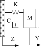
Fig.1
![]()
K: Spring constant
M: Proof mass
D: Damping factor
Y: Proof mass displacement
Z: ADXL05 displacement
X: Proof mass relative displacement
a: External acceleration
ω n: Natural frequency
Q: Quality factor
【References】:
1. James Doscher, Marketing Manager, Micromachined Product Division, "ADXL105: A Lower-Noise, Wider-Bandwidth Accelerometer Rivals Performance of More Expensive Sensors", (http://www.analog.com/library/analogDialogue/archives/33-06/adxl105/article.html )(2004/11/23)
2. Jorge Dias- ISR, University of Coimbra, "Sensing, Inertial Sensing", page. 5, 2004, (http://www.roble.info/pages/wis-print.pdf)(2004/11/23) .
3. Yazdi, N. Ayazi, F. Najafi, K., "Micromachined inertial sensors", This paper appears in Proceedings of the IEEE, pp. 1640-1659, Vol. 86, 1998. (http://ieeexplore.ieee.org/xpl/abs_free.jsp?arNumber=704269)(2004/11/23)
4. Performance Characteristics of Capacitive Accelerometers ( http://xenia.media.mit.edu/~verp/projects/smartpen/node41.html )(2004/11/23)
5. ABEPOH ( http://www.averon.ru/el/ic/products/ad/accel.htm )(2004/11/23)
2. Check out website http://www.evisual.org/homepage.html
and http://www.ardi.com/exe_win.php
to install required software for SCION on your PC. Look at the image " ADXL" . Using the SCION software, measure and calculate: (assume the movable proof
mass is 2 um thick polysilicon)
(a) The mass of the proof mass
(b) The spring constant of the tethers
(c) The resonant frequency of the device (compare to text, page 235)
(d) The contact pads are those rows of light squares on each side of the
proof mass. Assume all pads are shorted together. What is the total capacitance
between the proof mass and the pads? Ignore fringing for this calculation.
Sol:
First, we should use "Set Scale" tool (Fig. 2) to set the
HO scale
(100
μm
= 629 Pixels) (Fig. 3) , then we can use "Draw Lines" Tool and "Info Table" (Fig. 4) to measure the length in the picture.
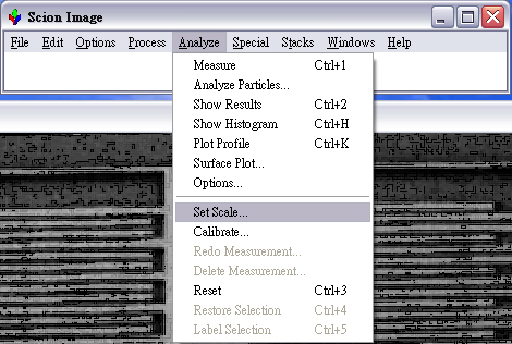
Fig. 2
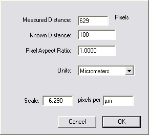
Fig. 3
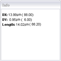
Fig. 4
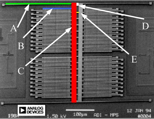
Fig. 5
(a)
We can separate the structure into five
parts, A, B, C, D, and E (Fig. 5). Then, the total area can be combined as

By Text book page 79, we have the density of Poly-Silicon. Than the mass of proof mass can be calculated.
![]()
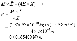
(b)
According to [2], the gap is 1
μm ( The gap I measured is almost the same) . (Fig. 6). Suppose that the acceleration of ADXL is 5 g (ADXL05 Measurement Range), and ignore the damper coefficient. The structure can be simplify to Fig. 7.
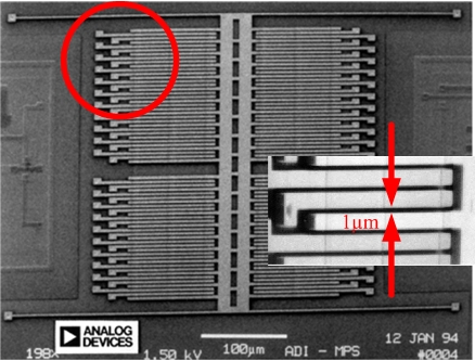 Fig. 6 Fig. 6 |
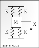 Fig. 7 |
Thus, the elastic constant K can be calcuated.
(C) The resonant frequency of the device can be calcuated.
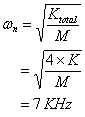
According to ADXL05-Specifications, the official frequency response is 12kHz. But my calculation is less than this value. This is because that I ignored the structure damper coefficent , and the proof mass I used is measured by myself.
(d) The contact pads are those rows of light squares on each side of the proof mass. Assume all pads are shorted together. What is the total capacitance between the proof mass and the pads? Ignore fringing for this calculation.
Overlapping finger length : 100 µm
Overlapping area: 200 µm^2
The gap: 1µm
Figer number: 40
By the parallel-plate capacitor equation in textbook page. 219.
Capacitance: 2 fF/Finger
Total capacitance: 80 fF
By Ref. [1] page. 8, the total capance=120fF , this is because that the total length in [1] is 150 µm, but we should use the overlapping length to calculate the capacitance.
【References】:
1. Bernhard E. Boser, " Surface Micromachining An IC-Compatible Sensor Technology", Berkeley Sensor & Actuator Center, 1996. (http://www.hotchips.org/archive/hc8/hc8pres_pdf/8.1.pdf) .(2004/11/23)
2. Michael Kraft, "Micromachined Inertial Sensors Recent Developments at BSAC", Berkeley Sensor & Actuator Center , 1998. (http://www.ecs.soton.ac.uk/~mk1/avstalk.pdf ) (2004/11/23)
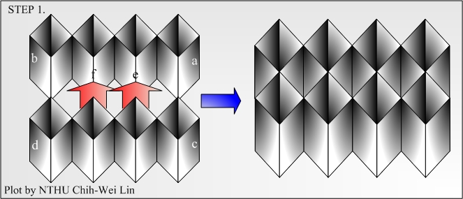
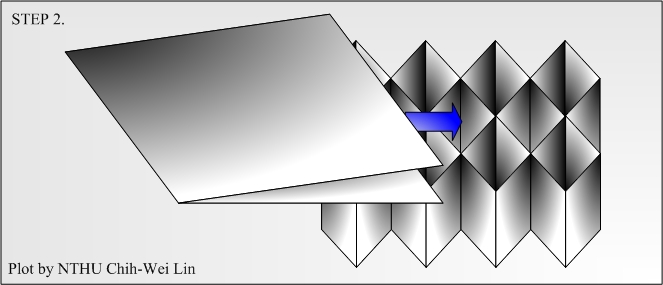
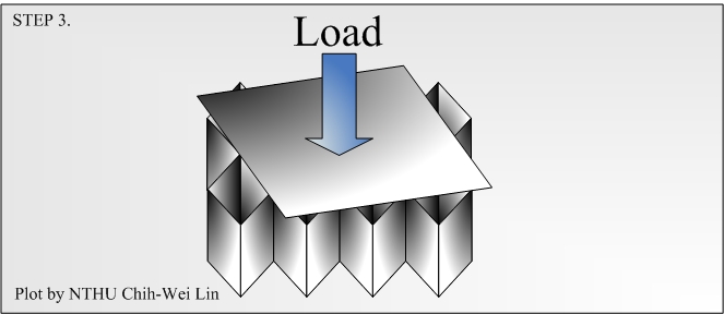
3. Given a single sheet of Xerox copier paper and a 30 cm length of half inch wide Scotch tape, design a structure to support as much weight as possible at least 5 cm above the surface of a flat, level, low-friction table top. You may:
(1).use scissors, razor blades, etc. to cut the paper and tape.
(2).apply tape to the table top
(3).choose how, when, and where the weight will be placed on your design
Not encouraged:
(1).Rolling the paper (tough to do with polysilicon).
(2).Cutting eparate pieces and assembling them later. Turn in a printout of your solution on class with solid lines where cuts are to be made, short dashed lines where the paper is to be folded up, long dashed lines where the paper is to be folded down, and outlines of tape attachment points. Attachment points should be numbered in order of suggested assembly, and with ``abc...'' markings to indicate which points are to be connected.
Bring your solutions to class on the due date for a live competition after class. Your structure may be partly or completely assembled when you bring it, but you must be able to place it anywhere (without any additional supports). In other words, you can't have it built and taped onto your own flat surface. Winning designs must carry the load for at least 10 seconds without collapse. Winners get extra 25 point credits.
Sol:
Before assembling parts, you have to down load the A4 word file (download) . Then, cut the paper following the lines, and following the dashed lines to fold up or down the paper. Cutting the 30 cm length tape to six pieces, and using the tapes to connect a to a, b to b, c to c, d to c...,e to e. Then, following the steps, you will own a powerful support structure (I hope).